
Valve
A device provided in a piping system to regulate or stop the liquid flow. Although many different types of valves are used to control the flow of fluids, the basic valve types can be divided into two general groups: stop valves and check valves. Stop valves are used to shut off or, in some cases, partially shut off the flow of fluid. They are controlled by the movement of the valve stem. Check valves are used to allow fluid flow in a system in only one direction. They are operated by the flow of fluid in the piping.
- Ball valve – Ball valves are stop valves that use a ball to stop or start the flow of fluid. The ball performs the same function as the disc in the globe valve. When the valve handle is operated to open the valve, the ball rotates to a point where the hole through the ball is in line with the valve body inlet and outlet. When the valve is shut, which requires only a 90-degree rotation of the handwheel for most valves, the ball is rotated so the hole is perpendicular to the flow openings of the valve body and thus the flow is stopped.
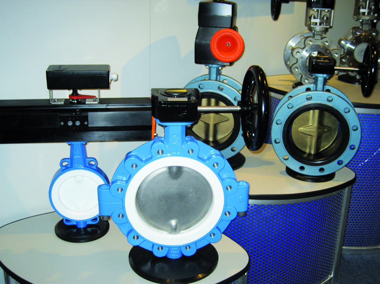
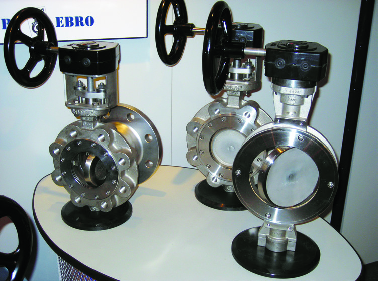
- Butterfly valve – A rotary stem valve with a centrally-hinged disc of the same diameter as the pipeline. The valve opens into the pipeline and therefore takes up little space, permits large flow rates and gives minimum pressure drop.
- Gate valve – Gate valves are used when a straight-line flow of fluid and minimum restriction is desired. Gate valves are named so because the part that either stops or allows flow through the valve acts somewhat like the opening or closing of a gate. The gate is usually wedge- shaped. When the valve is wide open, the gate is fully drawn up into the valve, leaving an opening for flow through the valve of the same size as the pipe in which the valve is installed. Therefore, there is little pressure drop or flow restriction through the valve. Gate valves are not suitable for throttling purposes since the control of flow would be difficult due to the valve design and since the flow of fluid slapping against a partially-open gate can cause extensive damage to the valve.
- Quick closing valve – Oil tank suction valves are arranged for rapid closing from a remote point. The collapsing of the “bridge” results in the valve closing quickly under the combined effects of gravity and an internal spring.
- Pressure-reducing valves – Pressure-reducing valves are automatic valves that provide a steady pressure into a system that is at a lower pressure than the supply system. Reducing valves of one type or another are found, for example, in firemain, seawater, and other systems. A reducing valve can normally be set for any desired downstream pressure within the design limits of the valve. Once the valve is set, the reduced pressure is maintained regardless of changes.
- Relief valve – Relief valves are automatic valves used on system lines and equipment to prevent overpressurization. Most relief valves simply lift (open) at a preset pressure and reset (shut) when the pressure drops slightly below the lifting pressure.
- Remote-operated valves – Remote-operating gear is installed to provide a means of operating certain valves from distant stations. Remote-operating gear may be mechanical, hydraulic, pneumatic, or electric. Some remote-operating gear for valves is used in the normal operation of valves. For example, the main drain system manual valves are opened and closed by a reach rod or a series of reach rods and gears. Reach rods may be used to operate engine-room valves in locations where the valves are difficult to reach from the operating stations.
- Safety valve – A valve that opens automatically in the event of excess pressure in a vessel, like a boiler steam drum. A safety valve is normally fitted with easing gear. Every boiler should have two safety valves mounted directly on the shell or steam drum.

