
POWER-SAVING DEVICES
- Wärtsilä EnergoFlow
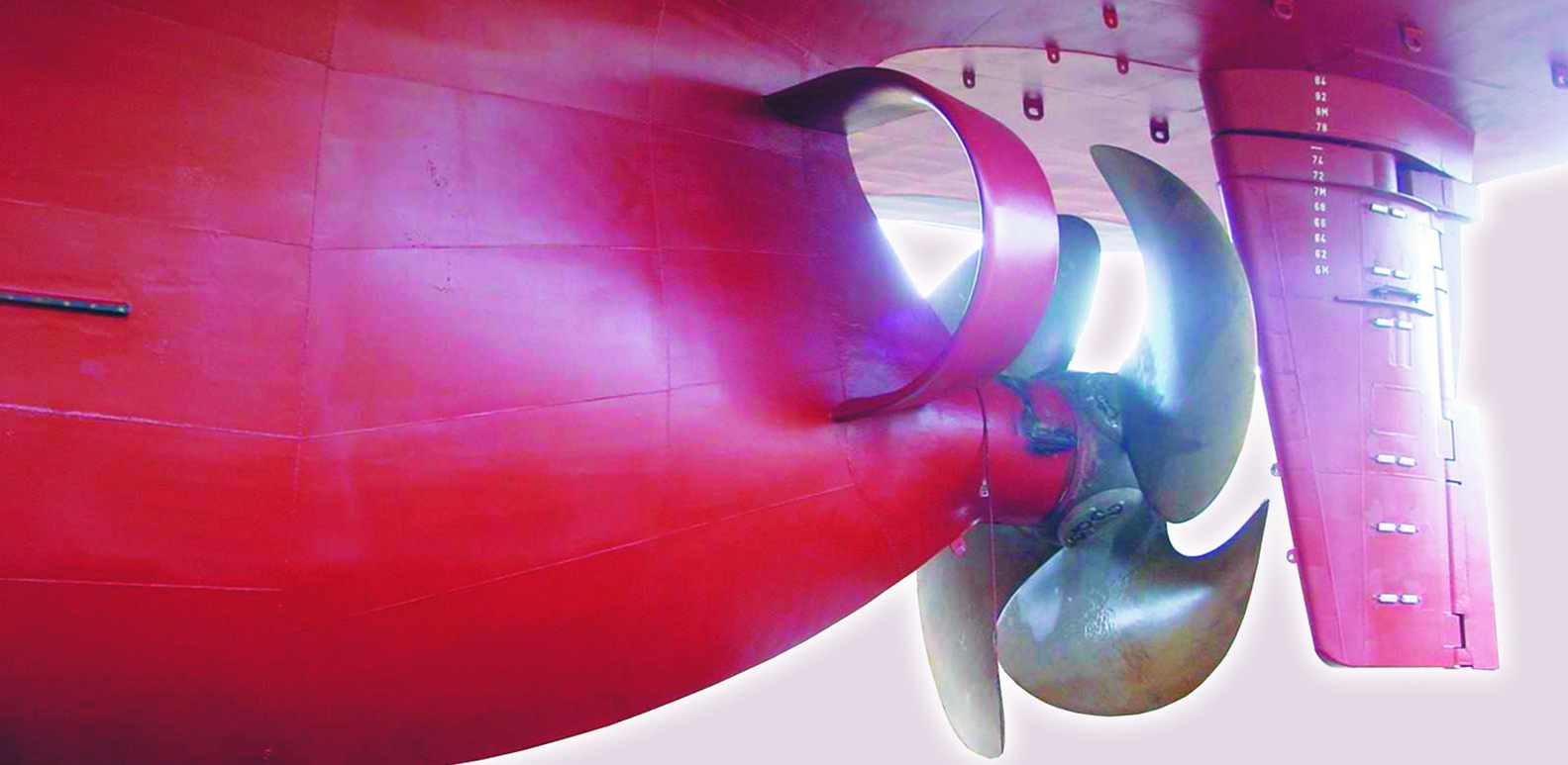
The propulsion improving device creates optimal inflow for the propeller by guiding one side of the stern flow in the opposite direction to the propeller rotation, generating pre-swirl. The solution consists of multiple curved fins and a ring attached to the ship’s hull to prevent the power losses that typically occur in a propeller’s slipstream. The curved fins enhance the propeller’s efficiency while keeping resistance at acceptable levels. The ring reduces the tip vortex and also levels out the peak stresses that occur in severe loading conditions such as slamming. As a result, less power is needed to propel the ship, leading to fuel savings.
- Wärtsilä EnergoProFin
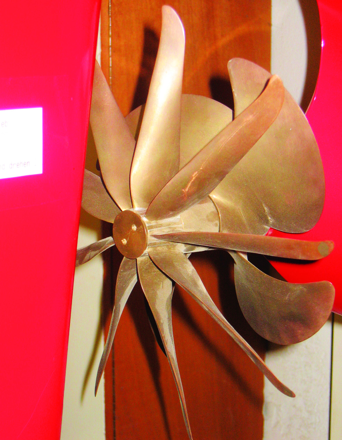
An energy saving device in form of a propeller cap with hydrofoil section fins, on the post-swirl side of the propeller. It can be easily mounted on fi xed pitch propellers (FPP) and controllable pitch propellers (CPP) and it rotates with the propeller. The EnergoProFin is designed to minimise the losses in the rotating fl ow leaving the propeller, by transforming rotational energy into e ective thrust, resulting in an e ciency increase that brings up to 5% fuel savings. Depending on the hull and propeller interactions, the payback time for the investment is less than a year.
- Schneekluth wake equalizing duct
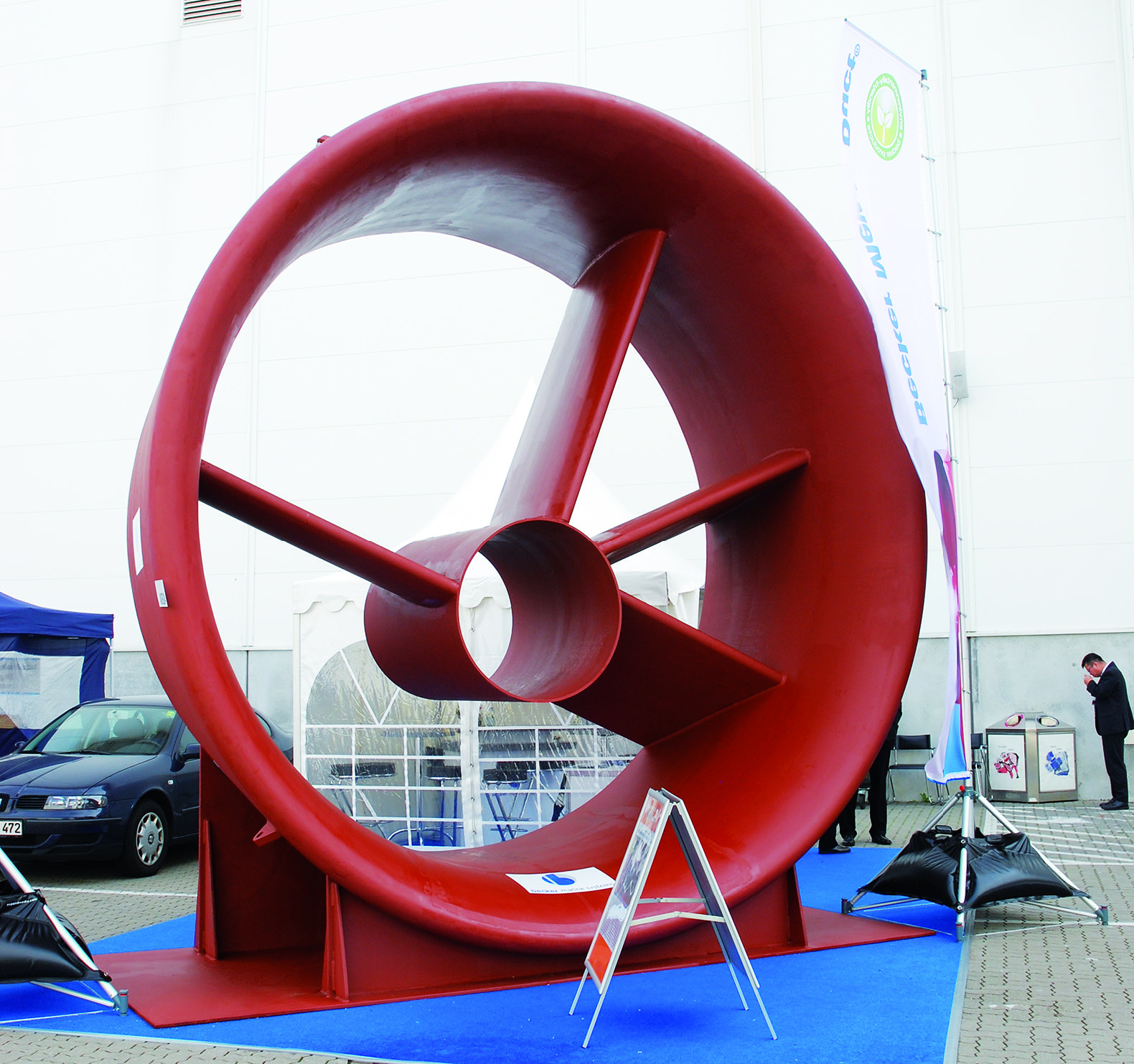
The propulsion improving device, especially for full block ships, developed by Professor Schneekluth. It consists of two nozzle-shaped halfring ducts installed on both sides of the stern ahead of the propeller. The duct accelerates the flow into the top half of the propeller plane and slow it down slightly in the lower part, thus achieving a more homogenous wake field.
- Mevis Duct (Pre-Swirl Duct PSD)
This power-saving device consists of a wake equalising duct combined with an integrated pre-swirl fin system positioned ahead of the propeller. It reduces losses at the inflow to the propeller by equalising the inflow via the duct, reducing slipstream losses through the use of pre swirl fins and reducing hub vortex losses by increasing the propeller load at the inner radii.
The PSD is suited to vessels with high block coefficient and speeds lower than 20 knots. This encompasses tankers and bulk carriers of every size, together with multi-purpose carriers and feeder type container vessels. The expected power reduction is in the range of 3 to 9%, depending on the propeller loading, and is virtually independent of ship draught and speed. A beneficial byproduct of the PSD is a small improvement to the ship’s yaw stability. Optimisation of the PSD is required on a ship-by-ship basis.
- Propeller boss cap fins (PBCF)
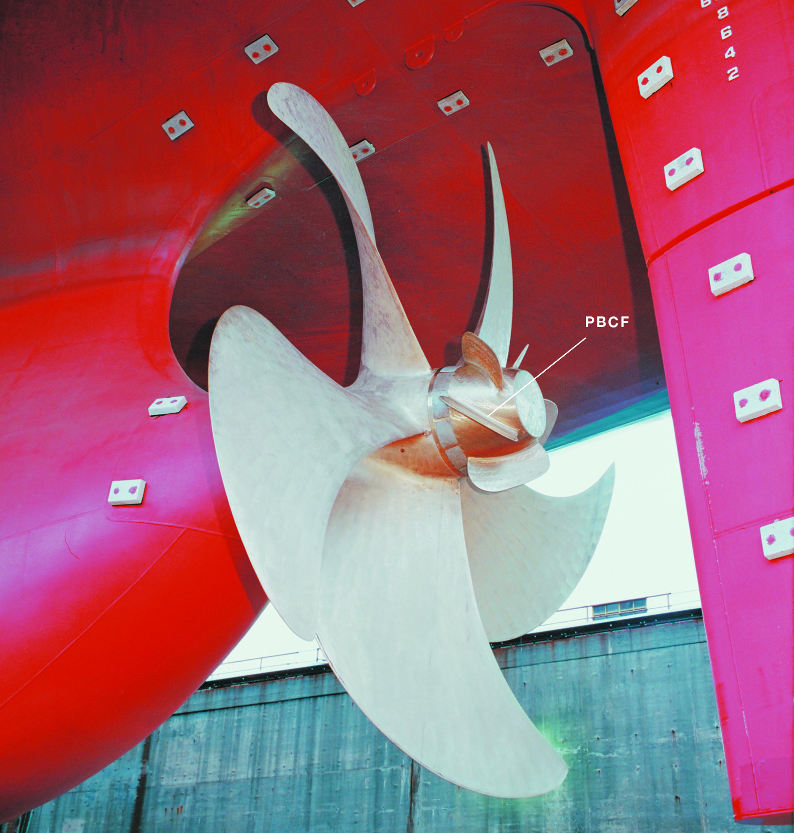
The energy saving device developed by Mitsui OSK. It consists of a propeller boss fitted with short blades inclined to convert hub vortex energy into additional torque and thrust transmitted back to the shaft. Propulsion improvements of 4%-5% are claimed, based on extensive service experience. The elimination of propeller hub vortex results in reduced stern vibrations and lower propeller noise. It also solves a number of rudder erosion problems.
Reported gains have to be considered with caution as the rudder significantly reduces the hub vortex and hence the gain in propeller efficiency due to PBCF.
- Grim vane wheel
Grim vane wheel is located immediately behind the propeller. Its diameter is somewhat larger than the propeller diameter so that only the inner part is located in the propeller stream. The vane wheel blades have turbine profiles in this inner section whereas they have propeller profiles at the outer blade section. In the turbine section, kinetic energy is taken from the propeller slipstream, which is directly transformed again within the propeller section into an additional thrust. In 1988 the world largest vane wheel: a freely rotating nine-bladed 11.65m dia propeller weighting 61t was supplied by Lips to IHI for installation behind the main propeller on 250,000dwt tanker.
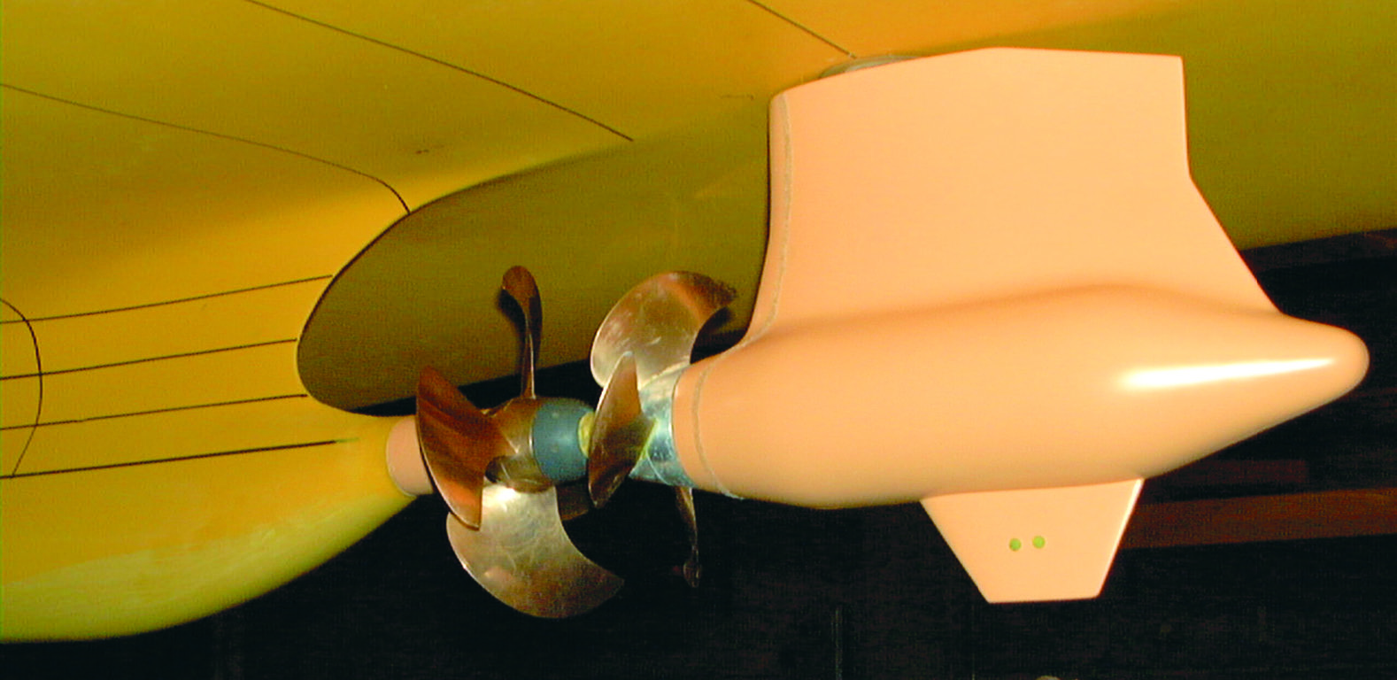
- Contra-rotating propellers (CRP) – Two propellers positioned in tandem on coaxial shafts that rotate in opposite directions. The after propeller of the pair is of smaller diameter to suit the contracting race column of the forward one. Higher efficiencies can be achieved with this propeller arrangement because no rotational energy needs to be left in the propeller wake. In 1988 the car carrier TOYOFUJI 5 was the first commercial vessel in the world to receive a CRP unit for evaluation purposes.
Ishikawajima-Harima Heavy Industries (IHI) has developed a large-sized contra-rotating propeller (CRP) system for container ships of between 4000 and 10,000TEU. After developing the large CRP system in 1988, IHI retrofitted it to the 37,000dwt bulk carrier JUNO the following year. Then, in 1993, the second system was fitted on the 259,000dwt VLCC OKINOSHIMA-MARU. This latest CRP was developed as a result of operational experience gained from these two vessels, but this one can work for twice as much transmission torque as that of a VLCC.
Podded CRP
The combination of the shaft-driven main propeller and the podded propulsor located on the same axis, but without any physical connection. The arrangement works as the contrarotating propellers and is said to give an improvement of over 10% in hydrodynamic efficiency for an ultra-large containership. A 25/75 power split between the pod and the main propeller is the best option from the point of view of total efficiency . See also CRP-Azipod propulsion of the ferry HAMANASU.
