An internal engine combustion performance may vary greatly from the values stated in its catalogue. It is therefore recommended to ask for more site-specific information from the vendor to have a better understanding of the expected performance of the machinery.
Comparing the output and efficiency values of different machines seems like a straightforward task. After all, what could be difficult about tallying different numbers and telling which one is higher? Well, it is not so simple when it comes to evaluating engines.
The efficiency of power generation equipment depends on a variety of factors, many of which are site- and application-specific. To make things more complicated, equipment suppliers often define their efficiency values for different reference conditions that are difficult to interpret for anyone other than specialists.
There are many factors which affect the actual performance of power generation machinery. The most obvious ones are the ambient conditions and the fuel quality. This means the actual performance of the equipment, when installed on site and commercially operated, will deviate greatly from the catalogue values. Those deviations will naturally have different characteristics, even for very similar equipment, depending on the design. This means that, say, even if machine A is more efficient than machine B in nominal conditions, it will not necessarily still be the case under actual site conditions.
To make things more complex, the nominal values are also often expressed for different sets of conditions or with different assumptions which may or may not be explicitly stated. This makes a realistic comparison, of the site performance for different engines, complex and time-consuming.
At a certain stage, it will inevitably require obtaining a more comprehensive data set from the equipment supplier that goes way beyond the single table given in a catalogue sheet. Yet, understanding certain general principles may facilitate early evaluation of equipment’s capabilities, even just with the information on the catalogue. Here, we take a closer look at those principles and its applicability to internal combustion engines.
Combustion engines are among the technologies most resilient to ambient environment changes. Nonetheless, at very high temperatures, the performance figures get affected. As a rule of thumb, it may be assumed that the performance parameters will be identical or very close to the nominal values for up to 30 to 35°C. Above that, the performance may get marginally impaired, both in terms of efficiency and output. Humidity also affects the performance. The higher the relative humidity, the lower the temperature at which the engine performance will start to deteriorate. The engines may also be sensitive to air pressure reduction related to high altitude.
Typically, catalogue parameters for engines are stated for the ISO 3046 conditions: an ambient temperature of 25°C, relative humidity of 30%, and an ambient pressure of 100 kPa. This means they are representative for operations in temperate to cool climates, with possible exceptions of the hottest or coldest days. However, for more extreme climates, especially for extremely hot and humid cases, derating and efficiency deterioration has to be always considered.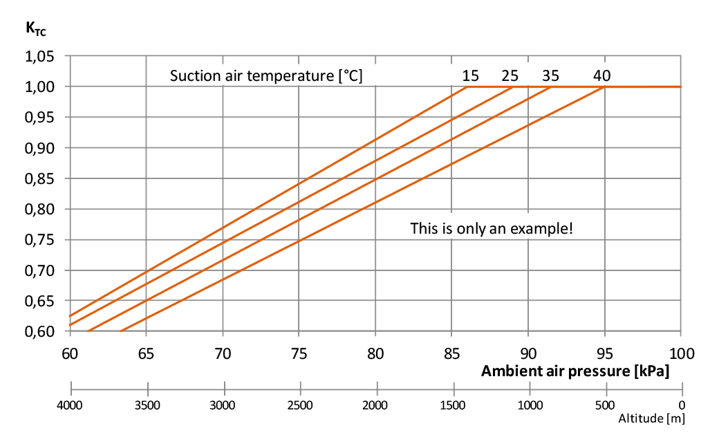
Fig. 1 - Ambient air pressure and temperature may affect engine output. Note that in the case of higher temperatures, derating starts already at lower altitudes. This shows how important it is to use complete information on the site conditions. (Click on the image for a full view.)
It is obvious that the efficiency of an engine depends on its load. This is particularly important for plants which are not expected to operate at full load for a considerable amount of time. Fortunately, in case of larger plants, combustion engine power plant allows one to achieve partial loads by shutting down individual gensets while keeping the others as close to the full load as possible. Nonetheless, sometimes, it will be necessary to operate the engines at partial loads due to other considerations (e.g. maintaining spinning reserve), and the efficiency will inevitably reduce. It may be noted though, that the efficiency curve of an engine is typically much flatter than that of other machinery.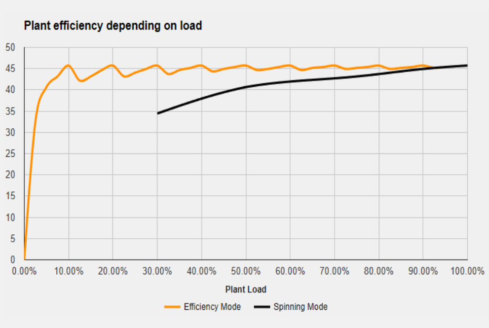
Fig. 2 - One of the outstanding features of the combustion engine technology is the flat load-efficiency curve. This diagram shows such curves for a ten-engine plant operated in two different ways. Orange curve represents the load control by shutting down individual engines while keeping the others at nearly-nominal load. The black curve represents a situation where all the engines are unloaded together, as is the case with plants which need to maintain a spinning reserve. (Click on the image for a full view.)
An alternating current generator generates not only active power but also a certain amount of reactive power. This is typically described by a value called the power factor (or, p.f.). The p.f. is a ratio between active power and the apparent power. The highest value of the p.f. is 1.0 and it corresponds to a purely resistive load. This is also the value when a generator, and therefore a genset, reaches its highest efficiency. In many cases, power factor equal to 1.0 is used as a point to define nominal parameters published in the equipment data sheets. On the other hand, in some other catalogue data, performance is defined for a relatively low value of 0.8, which is a typical generator design parameter.
Unfortunately, in real life, the power factor never sticks to those idealised values. In most applications, it is somewhere between 0.90 and 0.95. This means that if the nominal efficiency for the generator set is defined at p.f. = 1.0, the actual value will always be lower. And, if the nominal value is defined at p.f. = 0.8, then in real situations, it will be higher than what is given on the catalogue sheets. It is obvious here that if the values for two different machines are defined for two different power factors, they will not be comparable.
As in case of any other fuel combusting technology, internal combustion engines generate a certain amount of pollutants. In the context of performance, the most important group of pollutants are the nitrogen oxides, or, NOx.
NOx generation is an inevitable by-product of the combustion process, and therefore cannot be completely eliminated. However, there are methods to reduce it. In fact, the most recent environmental regulations require us to adopt such measures. There are two ways of doing it: the primary and the secondary methods. The primary methods focus on preventing the generation of the pollutant while the secondary ones involve cleaning the exhaust gases.
Modern combustion engines may use both primary and secondary NOx abatement measures. Secondary methods do not affect the performance of a generator set. The primary ones do, as optimisation of the combustion process to lower emissions carries a certain efficiency penalty.
Normally, the catalogue data for a generator set is given for machinery optimised to achieve its maximum efficiency, and therefore relatively high NOx emission. Gas engines are typically designed to meet a NOx target of 500 mg/m³N defined at reference oxygen content of 5%, also sometimes described as “TA-Luft” level, from a name of a 2002 German emission standard. Unfortunately, this standard is already outdated, and, in many jurisdictions, more stringent emission control is necessary.
Most gas engine designs can be optimised to meet stricter emission levels with primary methods, typically down to either “½ TA-Luft” or even lower, to 200 mg/m³ at 5% O2 (75 mg/m³N when expressed for 15% oxygen level). This corresponds to the current EU Industrial Emissions Directive. Such emission optimisation typically leads to a reduction of efficiency by some 1.0-1.5 percentage point. Of course, it is also possible to use an engine with higher efficiency, and SCR flue gas cleaning. Or a certain combination of both measures. The optimal solution is selected based on a project-specific techno-economic analysis, where the increased generation cost caused by the engine optimisation is weighed against the investment and operational costs of an SCR system.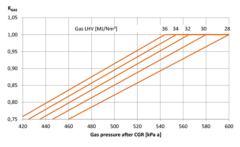
Fig. 3 - Derating of a gas engine is due to the fuel gas lower heating value. Note that, to some extent, LHV drop may be compensated with a higher gas supply pressure. (Click on the image for a full view.)
Like any other machinery, combustion engines also suffer from wear and tear and the engine performance deteriorates during operation. Fortunately, this deterioration, in most cases, is fully reversible during overhauls when the engines are brought back to their nominal parameters. Here, it is important to point out that in most designs the deterioration only affects the efficiency while output stays at nominal levels. Nevertheless, remember that the average efficiency of an engine plant will somewhat be lower than the nominal values specified for actual site conditions. The magnitude of that deterioration depends on the engine design and its maintenance programme.
Typically, combustion engines can tolerate a wide variety of fuel qualities and properties. Nonetheless, there are limitations. Some of these are absolute, in which case it is not possible or safe to operate an engine below or above a certain value. Others are conditional, which means that exceeding them is permitted but it may cause some derating or degradation in engine efficiency. Typical cases include the heating value or the methane number. Exceeding the minimums for those will lead to a certain reduction in output or efficiency.
Therefore, it is crucial to verify whether the considered fuel is within the standard specification. Otherwise, ask the vendor for performance figures that are valid for the particular fuel type.
This is the trickiest issue, which even many engineers may be unfamiliar with. Often in data sheets or catalogues, among conditions for which data is specified, you may encounter a statement like “ISO tolerance”, “tolerance as per ISO 3046” or “tolerance 5%”. It is directly related to a standard ISO 3046 ‘Reciprocating internal combustion engines – performance’. This standard stipulates that “unless otherwise stated, a higher [fuel] consumption of + 5% is permitted for the specific fuel consumption declared at the declared power.”
This means that if any fuel consumption value is stated “with ISO 3046 tolerance,” an engine may, in fact, have a fuel consumption up to 5% higher, and still technically meet the specified value. By extension, any efficiency declared with “ISO tolerance” may be 5% (note: not percentage points, but per cent) lower. For example, a generating set with a declared efficiency of 48.0% “with ISO tolerance” may, in fact, reach only 48.0/1.05 = 45.7%. In fact, it is more than likely that it will only reach such value. Historically, this tolerance was indeed provided to account for differences between individual engines leaving the production line. However, with modern manufacturing methods, these differences are, for the most part, a thing of the past. Now the concept of tolerance is – sadly – used to provide exaggerated efficiency values in many publications. Unfortunately, this is also a pitfall for those not familiar with the peculiarities of the engine business. It also creates a threat of comparing apples to oranges, when one data sheet contains 5% tolerance, and another does not. Thus, whenever a tolerance value is not explicitly stated, it is a good practice to ask the vendor to provide an explicit statement on tolerances, as the difference of 5% (that is, some 2.0–2.5 percentage points, depending on the design) is far from insignificant.
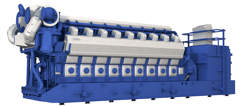 Fig. 4 - Some of the larger engine designs, such as this Wärtsilä 50SG or other Wärtsilä designs, are equipped with oil and water pumps are driven directly by the engine shaft. In some other designs, where the pumps are powered electrically it leads to an increase in the internal fuel consumption of the plant.
In the case of engine technology, the own electricity consumption is not very large. However, considerable differences may be caused by different designs. This is mostly because of pumps. Every engine needs some pumps to operate: typically, these are lubricating oil pumps, cooling water pumps and – if the fuel is liquid – fuel pumps. The difference is that in some engine designs, typically larger medium-speed engines, the pumps are driven mechanically by the engine shaft. This means that their energy consumption is “taken care of” even before the electricity is generated. But for some other engines, especially smaller high-speed designs that utilise electrical pumps, it will increase the own consumption of the plant.
Own consumption may also be affected by ambient conditions. This is because in most engine power plants, the waste heat is ejected through the radiators driven by electrical fans. Those fans, which are typically the largest consumers of electricity at such a plant, have their speed controlled to ensure proper cooling of the cooling water. The hotter the ambient air, the airflow needed is higher, which also increases the electricity consumption. As the actual consumption depends on site-specific conditions and plant configuration, it is normally not a parameter stated in catalogues. Therefore, it is recommended to ask for an estimated value from the vendors.
The bottom line is that “nominal” parameters, taken straight from a catalogue, almost never represent values that are achievable in actual site conditions even when all equipment is new.
While in certain cases (temperate climate, full load operation, no need for emission optimisation of the combustion process), it is relatively easy to convert catalogue parameters to values attainable in site conditions without extra knowledge. In other applications this will not be possible without asking vendors for further information.
This means higher catalogue efficiency of a certain engine type may not necessarily mean that the site efficiency of the design will be superior to its competitors even if the catalogue parameters are expressed for identical conditions.
Eventually, performance will have to be defined for specific operating conditions. It is therefore recommended to ask for more data points at the feasibility study stage of a power plant. This will make sure that the expected equipment performance is realistic for the considered site.
All values given in this article, particularly on diagrams, are only meant as an illustration of certain phenomena. They do not represent any particular product or design.
Once every six weeks, you will get the top picks – the latest and the greatest pieces – from this Insights channel by email.


