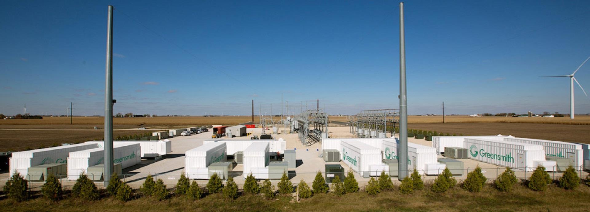
The Energy Storage Systems (ESS) market is witnessing a boom.
This spurt in growth can be attributed to price declines in energy storage technology as well as an increased need for storage due to global deployment of renewables generation. Most importantly, energy storage has become a conventional, grid-reliable resource.
The Aliso Canyon crisis in California shows why. In 2015, a major leak in the Aliso Canyon natural-gas storage facility in Southern California led to a high likelihood of power outages for the grid.
In the following year, leading energy storage vendors deployed three lithium-ion (Li-ion) battery-based systems with a total capacity of 70 MW / 280 MWh to compensate for the power capacity shortage owing to the Aliso Canyon leak.
Upon the successful completion of the projects, the commissioner for California Public Utilities, Michael Picker, said, “I was stunned at the ability of batteries and the battery industry’s ability to meet our needs. This was something I didn’t expect to see until 2020. Here it is in 2017, and it’s already in the ground.”
Estimates suggest that the ESS market is expected to touch USD 7 billion by the year 2025 against USD 1.5 billion in the year 2016, registering almost a five-fold growth.
One major barrier to growth comes from the risk associated with financing. While ESS solutions are tailored to operate for 10 years or longer, investors demand the solutions to deliver over their lifetime to accomplish considerable returns. The absence of meaningful data related to the long-term performance of grid-scale ESS coupled with uncertain markets for ESS leads to challenges of revenue forecasting. Owners of energy storage systems will thus have to ‘future-proof’ their deployments to maximise their return on investments (ROIs).
Limited track record
The energy storage database by the U.S. Department of Energy (DOE) lists only 14 grid-scale ESS projects, globally, that have an operating history of at least 10 full years. The average operational lifetime of grid-scale battery energy storage systems stands at four years and nine months.
This is perhaps because a large number of the systems have been operated as pilot projects to test a host of applications rather than running as full-scale mission-critical resources similar to the present-day systems. In addition, vendors roll out new energy storage products every 12–18 months, which means that past performance may not serve as an indication of future results.
Among ESS projects that have been operational for multiple years, the track record is mixed. To bolster the progress of grid-scale storage, the DOE invested in a nascent project in the ERCOT market to showcase the capability of advanced lead-acid battery technology to offer renewable firming and frequency regulation. The DOE’s objective was to procure technical and economic data from the project to gear up for future deployments.
Upon its installation, the operators found that the most profitable application for ESS was Fast-Responding Regulation Service (FRRS), a pilot program in ERCOT crafted to take advantage of the capability of fast-responding resources, like ESS, to alleviate grid frequency deviations.
Unfortunately, advanced lead-acid batteries turned out to be an unfavourable option for the case and the ERCOT ESS witnessed extreme degradation, which required replacement years before the expected end of the system’s lifetime.
Revenue uncertainty
Additionally, many of the vital electricity market services which ESS offers are garnered via short-term contracts.
Other important services are procured on a complete merchant basis via day-ahead bidding. This is in contrast to solar and wind asset investments, which typically generate stable revenue for investors via long-term power purchase agreements. ESS projects often generate revenue via ancillary services as well as capacity markets, which often do not come with long-term contracts.
The market value and procurement mechanism for these market services will change in unknown ways over the life of the ESS asset.
Faced with a limited track record of the ESS installation base along with revenue uncertainty, the only option for an ESS owner to mitigate risk is to future-proof existing ESS investments to plan for future changes.
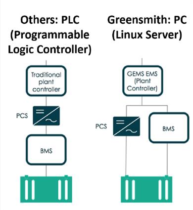
Fig. 1 - The PC-based approach communicates directly with PCS controller and BMS to abstract all technology characteristics and enable technology-neutral architecture.
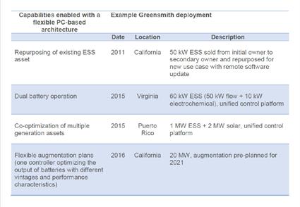
Table 1 - Case studies demonstrating the capability of a PC-based architecture.
What does future-proofing entail?
A crucial step towards future-proofing ESS involves deploying technology as well as project engineering that primarily focuses on scalability.
ESS projects can be future-proofed by: 1) installing a flexible controls architecture, 2) planning the right way for battery capacity augmentation, and 3) tracking ongoing operation with a flexible warranty.
Let’s start with architecture. There are two control architectures for ESS Energy Management Systems (EMSs): PLC-based and PC-based.
A programmable logic controller (PLC) is as a hardened industrial computer, designed originally for assembly lines. PLCs are ‘hard’ systems that are programmed to cater to specific tasks. They are programmed to accept limited inputs and outputs to achieve the task.
Modifications are possible, but they take significant time and effort and typically require an engineer onsite for months at a time. This makes the cost of PLC modification relatively high.
A personal computer (PC)-based controller is built on multi-purpose industrial servers and is controlled by software. (Figure 1)
PC-based architecture aids complex operation and optimisation and enables updates to be delivered quicker and at reduced costs. (Table 1)
The Greensmith Energy Management System’s control platform, for example, is crafted with a modular and technology-neutral architecture. This means the same controls platform can be used with any inverter technology and battery with minimum configuration.
A flexible control platform also allows flexibility to be embedded in ESS design through a battery augmentation plan. Battery augmentation involves leaving sufficient space at site for extra battery racks, and scheming cable and wiring trays for the future state of the system where some battery racks could be moved and additional racks added.
The challenge with battery augmentation is that old and new battery racks cannot be wired in parallel to the same inverter bus. If vintages are mixed, the newer battery racks are at risk of an overcurrent fault. A correct battery augmentation plan keeps new and old batteries separate, and with the management of new and old battery banks as separate systems. This management requires a flexible energy management system that can co-optimize distinct assets, which is feasible with a PC-based EMS. (Figure 2)
Finally, the battery warranty must be maintained despite any changes in operation profile. Li-ion battery warranties are complex. Warranty terms often include: energy throughput, peak charge/discharge rate, average charge/discharge rate, average temperature, maximum temperature across measurement points, etc. In addition, the battery management system (BMS) does not record these values.
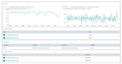
Without an understanding of battery degradation, battery owners cannot determine if it will be more advantageous to chase additional revenue, or rest the batteries to minimize degradation. The only way for system owners to make informed decisions is to track all revenue and battery health values using dashboards and analytics. These are core functions of the GEMS platform. (Figure 3)
Fig. 2 - Hypothetical augmentation scenarios. The charts assume a central inverter design, which is representative of most operating energy storage systems.
Fig. 3 - GEMS dashboard tracks values associated with warranty compliance; provides analytics as well as full data export capability (csv).
Case study of ESS future-proofing
ESS projects designed by Greensmith for the California market provide an example of future-proofing. ESS projects in California provide the state with a capacity service known as Resource Adequacy (RA). For energy resources that are limited such as ESS, RA contracts need to have four hours of discharge duration at rated capacity.
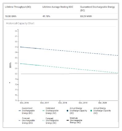
As part of Greensmith’s future-proofed ESS offering for California, GEMS tracks the warranted capacity of the batteries and displays trend values over time. At the same time, Greensmith designs for flexibility with a planned inverter-based augmentation in the middle of the system’s expected lifetime. If the owner chooses to run the system more aggressively for more revenue, this augmentation can occur sooner with more batteries augmented. Likewise, if the owner chooses to run the system less aggressively due to unattractive market conditions, the augmentation can be delayed or even skipped to reduce cost as much as possible. By tracking the battery’s flexible warranty, GEMS enables the system owner to make tradeoff decisions for various market conditions (Figure 4). This future-proofed offering was deployed as part of a 20 MW / 80 MWh project in 2016. (Figure 5)
This flexible approach provides an ESS owner with more confidence that merchant revenue is attainable, which boosts returns and allows for competitive bidding in RA tenders.
Fig. 4 - GEMS Analytics Dashboard showing forecasted battery capacity warranty based on battery usage scenario.
Fig. 5 - 20 MW / 80 MWh ESS in California with planned augmentation and flexible warranty.
Conclusion
ESS owners must plan to future-proof energy storage to take advantage of revenue streams that are not contracted. These revenue streams are uncertain, so a flexible system design is necessary to be confident that the revenue streams are attainable. In California, the risk includes merchant market revenue, which augments revenue from a bilateral capacity contract. Storage owners who do not consider extra merchant revenue in their operational strategy will not be able to compete in tenders for long-term contracted revenue.
Greensmith has focused on crafting a software technology and an engineering philosophy with scalability and flexibility in mind. Regardless of the changes that come to battery storage technology or energy storage market earnings, its solutions will be armed with the flexibility to achieve maximum results for storage operators. That’s the future.
Read the entire white paper:
Future-Proofing Energy Storage
Author: David Miller, VP of Business Development, Greensmith Energy, mail: david.miller@wartsila.com
Did you like this? Subscribe to Insights updates!
Once every six weeks, you will get the top picks – the latest and the greatest pieces – from this Insights channel by email.
