Liquefied natural gas (LNG) has taken a firm foothold as the marine fuel of the future, a fact that is clear to many stakeholders in the shipping industry. Despite this positive sentiment, the high investment cost for LNG storage systems is commonly cited as one of the major challenges in switching to gas. Wärtsilä continues to develop ways to combine technologies to create cost-efficient storage systems for gas-fuelled vessels of any size and installed volume of LNG.
Shipping is a truly global market, where competition is continuously increasing. The pressure from customers to reduce costs is further amplified by public demand to reduce the sector’s environmental footprint. Implementing innovative new solutions or adopting already existing technologies from other areas can be used as means to reduce costs and stay ahead of the competition. The latter option is typically more straightforward, with lower risks and a shorter time to market. Therefore, comparing the available technologies and their cost drivers can aid in devising methods to overcome implementation barriers. As a matter of course, every Wärtsilä solution takes into account each customer’s unique needs, but this review showcases a few of the ways that Wärtsila can help more customers take advantage of LNG’s environmentally and economically sustainable benefits.
Large LNG carriers have been designed with prismatic membrane tanks for several decades. Today, this design is the most popular LNG containment system for volumes over 100 000 m3. However, the high degree of sophistication required during onsite manufacturing, combined with the complex cargo handling system, has limited the success of the design as an LNG fuel tank.
At the other end of the scale, the most successful concept for gas-fuelled vessels has been vacuum insulated tanks. Vacuum insulation is the best insulation technology available, and is likely to remain so. A vacuum is maintained in the annular space between the two inner and outer tanks in order to reduce the convective heat transfer. In addition, the annular space is filled with an absorptive material to reduce the heat transfer due to radiation. With very low boil-off rates, the tank pressure can be easily maintained below the opening pressure of the safety valves for very small storage volumes. Therefore, vacuum insulated tanks will continue to be the preferred alternative for small LNG storage tanks below 240 m3.
The standard storage system for transporting various liquid hydrocarbons at low temperatures for several decades has been the IGC Code Type-C austenitic steel pressure vessels. The insulation was initially applied using polystyrene panels glued to the
outer surface of the pressure vessel. Today, polyurethane foam (PUR) sprayed directly on the surface is the leading insulation method, as it reduces the labour cost during the assembly of the panels on the outer surface. Foam spraying creates a homogenous
surface without boundary layers or sources for subsurface crack initiation and propagation mechanisms. Additionally, the lower heat conductivity of the PUR insulation allows a slightly better holding time with the same insulation thickness. A common
misconception is that insulation is fragile and sensitive and cannot be used without a steel canopy for weather protection. In reality, the insulation is covered by an outer fire resistant cladding, which creates a hard outer surface.
Many believe that PUR insulated tanks require large additional installation space. However, an insulation thickness of 300−350 mm is normally sufficient. Vacuum insulated LNG storage tanks are normally fitted with 250−300 mm annular space, despite the lower thermal conductivity. The actual constraint comes from the need to install the interconnecting pipes in the annular space, rather than from insulation requirements. In installations where fast LNG bunkering time is a necessity, the large bunkering pipes may result in an even bigger annular space.
Since the pipes laid in the annular space are almost impossible to inspect and can only be repaired by cutting through the outer tank, the pipe design undergoes vigorous engineering activity, including pipe stress and fatigue analysis, using finite element modelling (FEM). Since the inner tank is suspended in the outer tank, the movement and interaction of the inner tank with the outer tank is taken as boundary conditions for FEM calculations. In a similar way, the local stresses are analysed for both the inner and outer tank, where the forces from the piping impact the tank design.
Hence, a high degree of competence is required in each discipline, with numerous engineering hours before the design is completed. The design is then submitted to the nominated classification society for approval. Once the approval has been received, the long lead items, such as steel plates and castings, can be ordered. The high degree of technical sophistication inevitably increases the amount of engineering hours and, consequently, costs.
A vacuum insulated tank is, in principle, two pressure vessels, where one pressure vessel is installed inside the other, and a vacuum is applied in the annular space. The inner tank is designed to withstand the internal pressure plus an additional 1 bar of pressure for the vacuum in the annular space. The outer tank only needs to withstand the suction force from the vacuum, or the buckling force. For a cylinder, internal vacuum is more challenging to withstand than internal pressure. Therefore, the outer tank plate thickness is similar to the inner tank plate thickness. Eliminating the outer tank and applying PUR insulation can reduce the LNG storage system weight by approximately 40%, compared to a vacuum insulated tank design.
Similarly, the saddles for a single shell tank are simpler in design and can even be incorporated in the ship’s hull. It is possible because the saddles cannot come into contact with cryogenic LNG in any damage scenario, thus avoiding becoming brittle.
Consequently, the saddles can be made of carbon steel instead of stainless steel. This straightforward single shell mechanical construction reduces the engineering effort, saving large amounts of material. These cost savings can be directly transferred
to the end user, reducing the overall cost of the LNG storage system.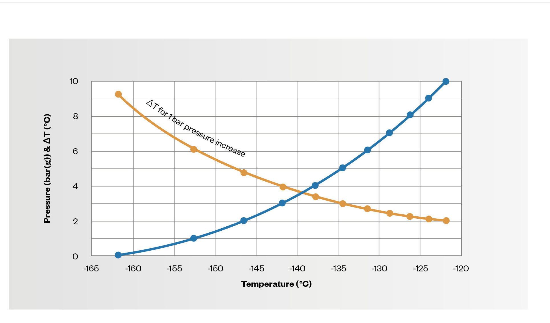
Fig. 1 - Tank pressure as a function of LNG (Methane) temperature. At atmospheric pressure, an increase of temperature with 9°C raises tank pressure with only 1bar, but at the end 2°C increase has the same affect.
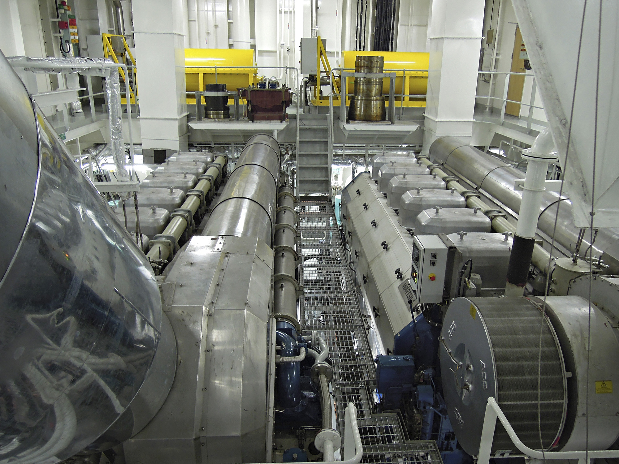
The various systems are fully integrated to achieve maximum efficiencies. Complete propulsion plant delivered by Wärtsilä including CPP, 2 x 6L50DF, twin-in single out gearbox, 2 x 6L20DF auxiliary gensets.
As heat leaks into the tank, LNG evaporates and slowly increases the tank pressure. The classification society requirement for a minimum holding time of 15 days regulates the minimum insulation requirements for an LNG storage tank. Figure 1 shows the equilibrium curve between vapour and liquid phase of methane from atmospheric pressure up to 10 bar(g). For single shell tanks, gas feed pressure to the consumers can be achieved with deep well pumps, described later in this article. The pressure and temperature in the tank can, therefore, be kept at the original LNG bunkering temperature. A pressure increase from atmospheric pressure to five bar would require an LNG temperature rise of 27°C. However, for medium-speed engines, sufficient engine feed gas pressure is typically achieved by pressurising the LNG tank to the engine operating pressure of approximately 5 bar(g), by means of evaporating a small quantity of LNG and feeding the gas back to the tank. The starting point for the pressure increase is thus the operating pressure of 5 bar(g). Due to the exponential nature of the equilibrium curve, the liquid at higher pressures absorbs much less heat. A pressure increase from 5 bar(g) to the maximum allowed pressure (10 bar(g)) results only in a net temperature increase of 12,5°C, in other words, approximately only half the amount of energy that can be absorbed in the upper pressure range. Thus, the lower pressure range is the most critical and partly compensates for the lower insulation properties of PUR insulated tanks.
The regulations for gas-fuelled vessels also allow gas consumption by engines and boilers, as a means to handle the boil-off gas (BOG) generated. The consumers of the BOG have to be available at all times; thus, power for the propulsion system cannot be considered as a gas consumer. However, electricity for the hotel load, generated by dual-fuel auxiliary engines or a generator connected to a main engine power take-off (PTO), may be added, provided that gas can be extracted directly from the LNG tank’s gas phase. Extracting the BOG from the gas phase will reduce tank pressure and consequently increase the holding time.
Here, the advantages of using Type-C tanks are evident. As the tanks are designed as pressure vessels, the BOG, therefore, can be easily fed directly to the auxiliary engines without the need for compressors.
A rectangular or prismatic tank is optimal with respect to space utilisation, but it cannot easily withstand internal pressure without adding stiffeners, etc., which add considerable weight and manufacturing effort. Therefore, a BOG re-liquefaction system
has to be installed in order to control the tank pressure. The re-liquefaction system substantially increases the investment costs and reduces the system’s feasibility as a storage system for gas-fuelled vessels. However, for LNG carriers, the
economy of scale reduces the auxiliary system cost per cubic metre stored, making prismatic tanks competitive above 10,000 m3. Several new designs and concepts are on the drawing board, and the first contracts have been awarded for small-scale LNG
carriers.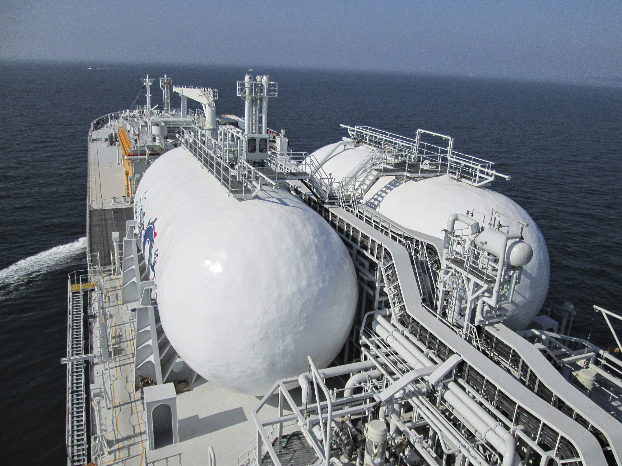
By engineering and supplying the complete cargo plant, the gas fuel supply system and the propulsion plant enables Wärtsilä to achieve optimal energy consumption efficiency for the entire vessel.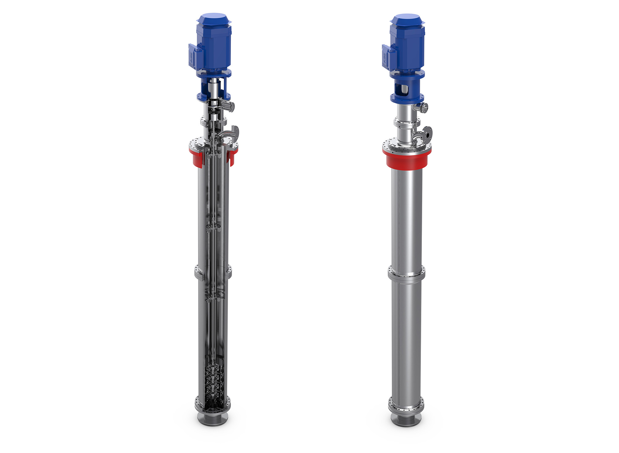
Wärtsilä Svanehøj ECA Fuel Pump with five years or 25,000 hours service interval. Pump can be retracted even with gas in the tank.
Medium-speed, gas-burning engines have been the favoured option for gas-fuelled vessels for almost two decades. Today, as the concept of operating on natural gas has matured, large 2-stroke engines are available on the market. Both the sizes of the vessels and of the prime movers, as well as the LNG storage volumes, are increasing.
The 2-stroke engine’s feed gas pressure requirements exceed the technical and economic feasibilities of simply pressurising the tank. The feed gas pressure is, therefore, preferably achieved by means of centrifugal pumps, which are reliable and do not require frequent overhauls. However, since liquefied gases are stored close to or at boiling point, maintaining a positive pressure on the suction side of the pump is crucial in order to avoid cavitation of the pump. If the pump is installed outside the tank, the sensitive, bottom-tank penetration needs to be protected, and the number of pipe bends before the actual pump has to be minimised.
Alternatively, installing the pump inside the tank creates an inherently safe design and eliminates a pressure drop in the suction line. However, maintenance of the submerged pump can only be done during a scheduled overhaul. Therefore, extra pumps are installed in order to achieve sufficient redundancy.
The Wärtsilä Svanehøj ECA Fuel Pump offers a number of new possibilities, including having no tank connections below liquid level, no electrical components inside the tank, and minimal contribution to the generation of BOG, since the electrical motor is installed outside the tank. Having less heat and pressure build-up in the fuel tank makes the new pump very safe. In harsher operating conditions, this system also maintains the pressure, thereby ensuring a continuous flow of gas to the LNG-fuelled engine. Furthermore, compared to conventional pumps with the motor installed inside the fuel tank, having the motor on the outside of the tank eliminates the transfer of as much as 70% of the electrical energy as heat to the LNG.
The design is based on more than 5000 deep well gas pumps in operation around the globe and will ensure a steady, safe, and reliable supply of gas to the engine, regardless of weather or thermal conditions. This pump is designed for a service life of
at least 25 000 operating hours or five-year service intervals. Should something unexpected happen, it also has a contingency in place, whereby the pump can be serviced under a ‘three service area concept,’ which enables access to the
motor, bearing and pump, even with gas pressure in the tank.
Today Wärtsilä is recognized as a leader in propulsion solutions for gas-fuelled vessels. The company’s strong and early commitment to this goal has created in-depth knowledge of the use of natural gas and LNG. There are several alternative
LNG storage systems available, which have already earned their place in the LNG distribution chain. Due to the better insulation properties, for volumes below 250 m3 the vacuum insulated tank will be the preferred choice in order to meet a holding
time above 15 days. However, the robustness and simplicity of the single shell design reduces both engineering and material costs without sacrificing system safety or integrity. It is, therefore, likely that the popularity of this design will increase
for gas-fuelled vessels in the 300−5000 m3 volume range. The business case for gas-fuelled vessels continues to become more attractive. Existing and new technologies are being adopted to help drive the total cost of ownership down and make LNG
an environmentally and economically sustainable propulsion solution.
Once every six weeks, you will get the top picks – the latest and the greatest pieces – from this Insights channel by email.