In field operation, generating sets are often subject to highly fluctuating loading conditions and anomalous phenomena imposed on the generator by the electric grid. Examples of such events are unstable grids with possible short circuits, heavily varying loading in peaking power plants, or frequency fluctuations in small power grids. Typically, the performance of the generating set for unstable grids must be demonstrated by fulfilling certain grid compliance requirements. Such tests are typically dictated by legislation and aim to assure that the generating set stays connected to the grid in the case of a transient event, such as a short circuit or an unwanted breaker opening in the grid. A typical example is to show that the generating set stays in the grid during a short circuit of a few hundred milliseconds.
For the operator, this translates directly to increased uptime of the power plant and increased reliability in energy production. On the other hand, running through such heavy transients imposes elevated load levels on the engine and generator components. To guarantee that a given engine will perform under all possible loading conditions during the operational life, simulations are the only viable choice to assure that such elevated loading does not affect the component lifetime negatively. Similarly, understanding and being able to simulate such events helps us to better design the equipment for specific customer loading conditions and business demands.
Although grid compliance issues are typically related to power plant applications, one faces very similar challenges in marine applications as well. In the marine operating environment, the internal grid of the vessel is small, which also leads to highly fluctuating loading conditions, particularly in special applications with highly varying power output demands, such as dredgers. Adding to the complexity are installations where there is both mechanical propulsion and electricity generation coupled to a single engine. In such conditions, the generating sets should be able to respond to the load changes rapidly enough to avoid destabilising the vessel electrical system. In addition, hybrid applications are becoming more common, further underlining the need for modelling. Moreover, in marine applications, safety typically plays a key role. As well as providing the best possible economic output through increased efficiency to the vessel operator, tightly coupled mechanical and system simulation models help in assuring the safety at sea of the equipment – even under the most severe loading conditions.
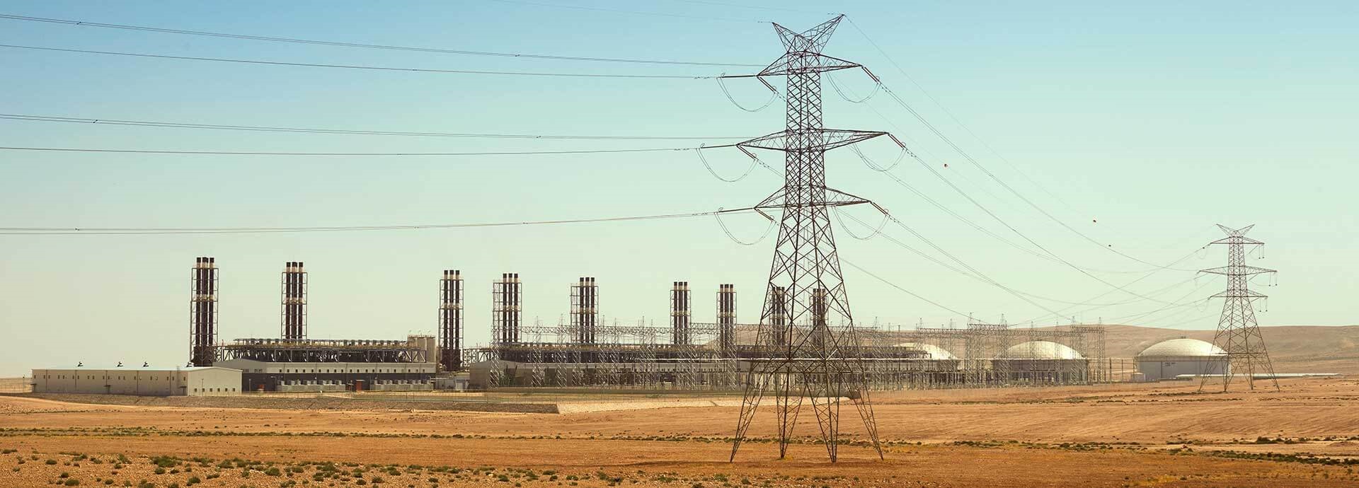
In this test case, we take a closer look at the 20-cylinder Wärtsilä 32 engine. This is a typical engine used in power plant installations, usually comprising several such generating sets. When coupled to a small grid, such as on a stand alone island application, the interplay of the generating set and the control system becomes one of the determining factors of the genset performance. Consequently, understanding the coupled transient behaviour is of utmost importance when designing generating sets for such demanding conditions. Typically, a generating set, after reaching the target speed, runs at a constant speed to produce electricity of a constant frequency. It is essential for the frequency of the electricity to remain as close as possible to that of the grid to ensure it stays in synchronisation with the grid. As the generator rotor and crankshaft are directly connected by a flexible shaft system, any higher variation of the crankshaft speed induces a variation of the rotor speed and, consequently, of the induced magnetic field. Such variation can come, for example, from an unwanted variation in the cylinder pressure or from a non-constant electrical grid. Therefore, even for a demanded constant speed, the rotor speed needs to be controlled by manipulating the injection quantity and ignition timing.
To accurately simulate transients, such as whether the generating set will survive a short circuit without falling off the grid, one needs to consider the engine mechanical model as a coupled model with corresponding automation and electrical models. Consequently, this coupled model will not only serve the needs of mechanical simulations, but it can also act as a testbed for more refined control system development in a virtual environment, thus delivering better solutions to the customer in a shorter amount of time. In the daily operation of a generating set in a power plant or marine installation, such high transient effects play an important role and are demanded to be considered in the development of the engine control system.
To cover such effects as described above, a highly complex system, covering the correct signal flow and controls, is required. But, as the simulation targets are still component durability, bearing analysis and vibration control, the considered sub-systems, structures and their interactions must also stay on the complex 3D level. A simplification of the mechanical model, as used for pure signal-flow simulations, is simply not valid for this type of simulation. Therefore, the next step in virtual development and validation is a virtual model for multibody simulation coupled with control systems and an online load generation algorithm. The target is to simulate how the whole generating set responds to predefined network events, such as short circuits, to satisfy the needs and requirements discussed above.

The idea of the virtual model approach is to realise a simulation model that is as near as possible to real-life conditions. Thus, all important influences on the electro-mechanical system of the engine and generator are to be considered as an integral part of the complete generating set before any real parts are produced. During the product development process, the real-life conditions need to be verified to have confidence in the applied procedures and methods to assure the performance of the final product.
There are also obvious obstacles to implementing physical testing of all possible application cases throughout the complete system in the early development stage. Furthermore, there are limitations on the possible scenarios to be tested, due to, for example, the massive equipment needed to replicate a network transient on a 10 MW genset. Further considering some typical problems in testing, such as the large variety of installations with a different controller calibration, the virtual approach further shows its great potential and value. However, it must be noted that testing is always needed in calibrating the models, but the main advantage is the ability of the model-based approach to reach even those hard-to-test conditions which one often encounters in practice in field applications.
From the simulation point of view, the virtual model consists of a complex mechatronic system with four distinct subsystems:
Mechanical
Electrical with controlling
Pressure supply
Engine control
Figure 1 provides an overview of these subsystems and the signal flow with the required control loops, considering the load demand as input signal, the required cylinder pressure for each cylinder, the resultant crankshaft speed, and transition to the rotor speed which is the control target, induced electromagnetic forces and output torque, and the electric current, voltage and frequency. The mechanical and electrical subsystems (1 and 2) are computed in the multibody dynamics software EXCITE Power Unit. The pressure and load map calculation and load control (3 and 4) are computed in Matlab/Simulink. Both simulation platforms are coupled via co-simulation by means of an S-function in Matlab/Simulink.
For a proper dynamic response of the genset drivetrain, we consider on the mechanical side both the linear flexibilities of the mechanical components and the nonlinear behaviour of drivetrain components, such as bearings, mounts and coupling. In addition, for the generator we consider the electro-mechanical behaviour of the generator including electrical control and the behaviour of the high voltage grid. To complement the methodology, online load generation of the engine including engine control is included.

The test consists of a steady state condition with an intermediate short-circuit for 100 ms, which is modelled as a sudden decrease of the load resistance, as demonstrated in Figure 2, which outlines this simple test case. Figure 3 shows the change of the angular velocity of the rotor during a short circuit after an initialisation period of three seconds for stabilisation of the entire system. Within the short circuit event, the speed first decreases, then increases and finally starts to stabilise again. Mechanical power enters a strong transient and then stabilises. Results for voltages A/B/C of the three phases are visible. The voltages are again very sensitive to the applied short-circuit resistance.
Also, one can see the change of angular velocity at the end of the crankshaft during the short circuit. Like the rotor shaft, after a period of initial stabilisation, the speed first decreases, then increases and finally starts to stabilise. The transient reaction at the cylinder loads are clearly visible. First, the engine tries to reach the target speed by applying full load. This is the initial start-up and stabilisation phase. During the short circuit the engine applies full load again due to the torque peak during the short circuit, trying to reach the maximum torque. All the results agree qualitatively very well with the phenomena witnessed in measurements.
This novel approach for investigating generating set grid compliance clearly agrees well with reality, given that the model parameters are correctly calibrated. One of the greatest benefits of such a model is the ability to simultaneously analyse the mechanical structure, including the stresses imposed on the components, directly together with the control system, and how they perform under different loading conditions.

Once every six weeks, you will get the top picks – the latest and the greatest pieces – from this Insights channel by email.