With its long history of technology leadership in advanced controls for medium- and low-speed combustion engines, Wärtsilä pushes boundaries with its second generation UNIC system and enables new performance leaps for the Wärtsilä 31 engine. This article is based on the award-winning paper “Next generation UNIC automation system to enable Wärtsilä 31 performance” presented at the CIMAC Congress 2016.
Monitoring and controls for Wärtsilä engines have evolved since the 1970s from off-engine monitoring and alarm systems to an embedded engine control system. Control functions, such as electronic fuel injection, were introduced along with the common-rail and gas engine introductions. Around 2002, past automation system products had become increasingly demanding both to maintain and to use as basis for new product development. 1 Hence, the strategic decision was taken to develop a generic platform, UNIC, to be used on all Wärtsilä 4-stroke portfolio engines. However, older systems, such as the WECS 2000, 3000 and 8000, are still in active use on field engines.
With the introduction of UNIC, several high-quality, strategic design concepts were developed. These main concepts also use the second generation UNIC as a foundation.
On the hardware side, the main characteristic is the on-engine modular and distributed design. For wiring, connector-less, point-to-point cable connections and the so called “flying lead” concept are retained since they have proven their superior reliability compared to wiring-harness based solutions.
The modular system architecture, Wärtsilä Modular Application Platform (WMAP) design, continues as the software platform basis. Furthermore, model-based design principles, as well as a large part of application functionality, have proven their robustness and continue as part of the foundation. This proven and robust infrastructure functions as the stepping stone for new functionalities introduced.

Fig. 1 - System overview
The need for flexibility grows along with increased variation in customer needs and the ever-changing market environment of today. Flexibility on the control system side comes in the form of the modularisation of hardware and software. Of equal importance is the flexibility with respect to changing operational profiles, both long- and short-term.
Hardware-wise, the second generation UNIC is comprised of various modules with specific features – a Cylinder Control Module (CCM), Input/Output modules (IOM), and a safety module (ESM) – as well as a system interface consisting of Communication modules (COM) and local display units (LDU). (Figure 1)
With these building blocks, the system can range from simple, single-module speed/load controller applications up to any number of cylinder configurations, e.g. a 20V SG gas configuration with a total number of 12-14 modules. (Figure 2)
With multi-purpose input/output channels, an optimal number of modules builds up the system configuration to provide a cost-efficient solution. With the modularisation on the engine side, automation modules for each engine module can be mounted and pre-tested step-by-step, ensuring a solid validation chain.
With a platform software as its basis, the architecture is a modular hierarchy. The platform, together with application modules and configuration, forms the product-specific package. Maximum reusability is achieved when the platform is common for all, and application modules and configuration are selected depending on the product-specific needs.

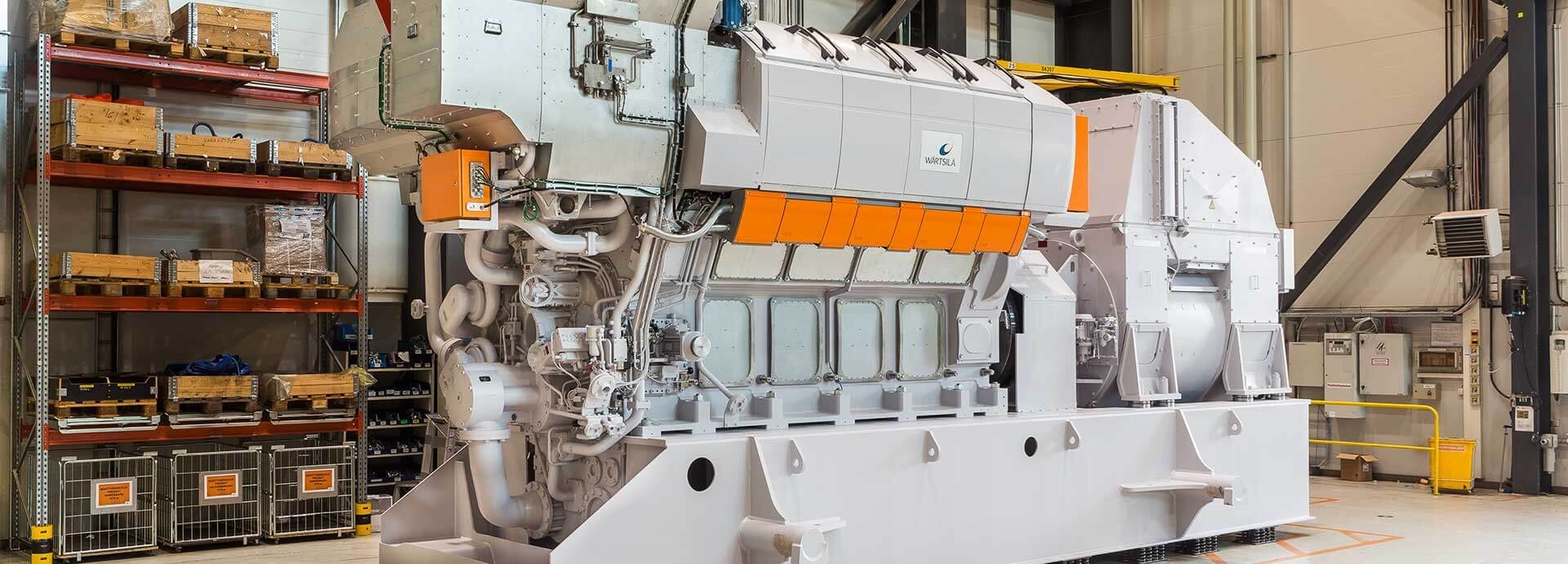
Fig. 2 - Wärtsilä 31 with second generation UNIC system
Operational flexibility and capability to account for changing conditions, e.g. changing fuel type, provide a smooth transfer to new conditions, immediate real-time operational changes, as well as upgrades of system capabilities, e.g. retrofit value packages. With the modular architecture, for upgrades, such as fuel type changes, the automation system is easily rebuilt with additional control modules and functionalities. Furthermore, the extensive capacity of the second generation UNIC enables introduction of new functionalities for full flexibility in real-time operation, such as enabling smooth changes between fuel types.
Engine availability plays an increasingly important role in many engine applications. The second generation UNIC system considers availability through its architecture, design and diagnostics.
A typical engine control setup includes at minimum two COM modules to provide redundant connection interface for vertical and horizontal integration (Figure 3). Due to a dual-connection interface, connectivity to engine control always can be secured in case of a single failure. Two LDU displays can be mounted to ensure redundant local control.
Increased communication bandwidth enables easy data and control distribution within the distributed engine control system. Control execution can be synchronised to enable true redundant controls in case of a single point of failure.
In addition, improved availability is secured through improved diagnostics and prognostics. For example, the electrical actuators used in the Wärtsilä 31 installation can provide prognostics data to detect possible service needs before actual failure. This enables planned condition-based service when it is most convenient for a customer’s operation schedule.
The UNIC system introduces a new level of reliability, which, along with high quality, is of utmost importance for the introduction of additional control demands in its second generation. Based on the experience from past system generations and new design quality assurance methods introduced in electronic design, a robust design of a second generation UNIC was created.
Wärtsilä continues to ensure automation component availability throughout the life cycle of Wärtsilä engine products. The electronics life cycle is getting shorter, due to the overall trend set by a high-volume consumer electronics business. The automation component availability challenge is addressed by careful electronic component selections, long-term obsolescence forecasting and obsolescence strategy implementation to secure engine control spare part availability. 2

Fig. 3 - Systems integration
Traditionally, electronic design selections have been based on component ratings and good design principles. During the prototyping phase, the design has been validated and the outcome taken to the next design iteration.
With today’s simulation methods 3, it is possible to ensure design even before the actual prototype. Design failure rates can be simulated and forecast several years in advance. Most critical improvements can be done even before the first prototype.
By setting the product design reliability at an acceptable level, an improved validation chain has been used to ensure the design quality of the second generation UNIC automation components.
With the previous UNIC generation validation experience as a basis, the automation component validation methods have been further developed and are today fully integrated into internal component release processes. In addition to on-engine operational testing, the validation process includes functional-, endurance- and accelerated ageing-testing. 4 For example, Highly Accelerated Life Test (HALT) 5 has been actively used, throughout the design cycle of the components, and proven to be a good validation method to detect and improve possible weak points in the automation design. (Figure 4)
Automated functional validation of the engine control system has supported efficient design cycles and good validation coverage. Overall results show a significant increase in the quality and maturity level of components. 4

Fig. 4 - Accelerated agieng test - HALT
Wärtsilä’s long experience in automation electromechanical design provided a solid base for the electromechanical design for the Wärtsilä 31 engine. Feedback from field experience has been consolidated into updated design guides and applied to the Wärtsilä 31 automation design to ensure high reliability as well as easy serviceability of the engine controls. The cable layout and routing of the engine automation components were considered in the engine mechanical design. Special attention was also paid to temperatures, vibrations, oil and avoiding sharp edges. Potential vibration issues of the engine control and automation modules were tackled by using proven wire rope dampers.
A new electronic module enclosure, WTB-20, was developed for the Wärtsilä 31 engine. In addition to providing proper IP protection for the electronic modules, one of the cornerstones for WTB-20 design is the lean mechanical fit to Wärtsilä 31 as well as easy accessibility for service and maintenance purposes. The enclosure provides easy access to all measurement and control signals, and enables easy spare part replacement. Heat dissipation simulation was also closely considered in the WTB-20 enclosure design. (Figure 5)

Fig. 5 - WTB-20

Fig. 6 - Local Display Unit (LDU-30)
It is important to lower the complexity of the system to improve its usability for operators. In the second generation UNIC system, a new Local Display Unit (LDU) is introduced, along with improved diagnostics.
LDU-30 was developed with a strong user focus, interviewing Wärtsilä service and customer representatives. Input from these interviews was consolidated to develop the LDU-30 usability and industrial design. (Figure 6)
LDU-30 provides an intuitive user interface with touch controls to easily browse through basic engine and measurement statuses. The LDU-30 light guide enables easy engine status indication through intuitive status colouring and blinking schemes, which guide operators through the desired controls and maintenance checks for Wärtsilä engines. Further, it enables a deep dive into engine measurement details and visualised engine diagnostics information when needed.
From the maintainability and service perspective, LDU-30 provides easy access to the engine process data and alarm log. Convenient data export and software update functionalities are provided through an integrated USB port.
From a usability point of view, it is important to have a similar look and feel, from a vessel-bridge or a plant-control level all the way to the machinery. It is important that the control functionality and information presentation are provided in a similar fashion, independent of which Wärtsilä equipment the operator is using. Therefore, the Wärtsilä look and feel are aligned in the design of all machinery interfaces. This also has been one of the key elements in the LDU-30 design, mirroring the Red Dot Award-winning 6 Wärtsilä propulsion control panel design in various ways. (Figure 7)
While engine control functions are getting more advanced with more measurements and actuators added to the system, the increased complexity makes troubleshooting of engine functionality and controls more challenging. Traditionally, several individual alarms may be triggered due to a single failure in the control system. The improved capacity of the second generation UNIC system can now combine different alarms so that operators or service personnel are able to pinpoint the actual root cause for the failure. It also extends overall diagnostic functionalities, including stiction detection and cooling diagnostics. 7
In addition to easy spare part replacement enabled by WTB-20, the second generation UNIC-controlled boot-up enables automatic software download and data synchronisation. When a spare part module is installed on the engine, UNIC automatically detects this and downloads the correct software for the module when it is safe to do so. When the module boots up with the new software, the system takes care of synchronising the system status and process data on the control module before it enters the operational mode and starts to control the engine. This enables safe and easy module replacement without powering off the entire engine control system.

Fig. 7 - Double local displays
Due to several drivers, such as tightening emission legislation, fuel consumption, variations in fuel quality and overall performance, great effort has been put into the second generation UNIC to optimise the closed-loop controls to achieve fast-acting and robust control dynamics. From a design point of view, it is very important that all aspects of the closed-loop control chain work together in an efficient way. Things that at first may seem unimportant or trivial can have a huge impact on the end result. It is not enough to base the system on solid control algorithms if other parts of the measurement or control chain fail. To optimise controls, it is important to identify the key aspects of the system that influence the control dynamics 8 and those for which design can make a difference. In this case, the main aspects are the following:
Each of these needs to be designed with precision to ensure high control quality. The second generation UNIC hardware enables improved timing restraints for measurement sampling, updating the control algorithm, driving the actuator control and increasing the speed and determinism of the communication network. This enables the system to move big amounts of data back and forth, which is partly a prerequisite for building solid control applications.
There has been significant effort in control development to improve the measurement quality. For example, the FPGA (field-programmable gate array) hardware provides an excellent platform for different types of signal processing, such as the anti-alias handling of measurement data. These improvements have shown a clear increase in the overall measurement quality, which also has a direct influence on the robustness of the different control loops.
With the well-proven foundation of the UNIC system, it is important to ensure that the different control modules of the system are synchronised to maximise their functionality. With efficient communication between control modules, it is possible to fulfil strict timing requirements and to ensure that control algorithms are provided with valid measurement data. The result is that the output of the controllers also reaches the actuators of the system without significant delays.

Fig. 8 - Closed-loop controller
Trends in engine control show a clear shift in focus – from steady-state control towards transient control. 9 The engine’s ability to move fast between different working points is something that is carefully monitored nowadays. Even though robust steady-state control is still very important, the ability to react rapidly to changing conditions also must be a part of the normal control routines, making transient control algorithms necessary.
To get a fast transient response from more traditional steady state controllers, different types of feedforward controllers have been introduced. A feedforward controller is normally implemented in parallel with a closed-loop controller to react on process disturbances 10 (Figure 8). For this, a fast measurement of a process disturbance is needed for the feedforward part of the controller to react to the disturbance before it is seen in the controller feedback. Though the process disturbance is not always measurable, it might still be possible to use feedforward control to achieve a good transient control response.
For example, pressure controls have significant potential for transient improvement. Typically, for a closed pressure control loop, the pressure in an enclosed volume is controlled. The pressure within the closed volume is measured and used as feedback for the closed control loop. Then the controller sets the position of the flow control valve to change the mass flow into the volume. In this case, the mass flow out of the enclosed volume can be seen as a process disturbance. Even if not measurable, it is important that the system also controls the mass flow out of the enclosed volume. This information can be used directly by the feedforward controller to improve the transient behaviour without additional measurements. With this type of feedforward control, the mass flow into the enclosed volume is compensated by the outgoing mass flow, even before the measured pressure changes. (Figure 9)
Different types of feedforward components can be used, depending on the circumstances. For example, the static relation between the flow control valve position and the mass flow out of the volume can be used. Other possibilities can be used to avoid the additional calibration of the feedforward element, e.g. self-tuning maps for keeping track of the relationship between the valve position and mass flow.
In other cases, the feedforward controller does not necessarily depend only on a single signal. In such cases, an elegant solution is to use dynamic process models to further improve transient behaviour of the controller, such as to create virtual disturbance measurements that can be valuable for the transient controllers. A typical example could be the air-to-fuel ratio, which can provide vital information to several controllers in the system, e.g. an adaptive air-to-fuel limiter to optimise the gas admission to the cylinders during transients to accommodate for turbo-lag.

Fig. 9 - Feedforward add-on for closed-loop pressure control
In-cylinder pressure measurement is widely used nowadays for research and development of internal combustion engines. It is said that the cylinder pressure characterises the heartbeat of the engine and that it is an enabler for meeting future demands of internal combustion engine performance.
With the recent development of cylinder pressure sensors, the in-cylinder pressure measurement is finding its way onto production engines, where new, innovative ways to control the engine can be applied 9. The in-cylinder pressure contains information that characterises the combustion behaviour, which then indicates that the many different feedback signals, together with the correct extraction algorithms, can be used for controlling the combustion in different ways. Generally, the most used combustion parameters extracted from cylinder pressure measurements are the indicated mean effective pressure (IMEP) and heat release (HR). From the cumulative heat release, it is possible to gain valuable information about the ignition delay, combustion duration and, perhaps most importantly, when combustion takes place in the cylinder.
The second generation UNIC control system supports the calculation of all the above-mentioned combustion parameters that will be essential for future combustion control concepts. The combustion parameters provide new means for further exploration of cylinder balancing, for example. Cylinder-wise combustion control can even be used to balance mechanical differences between the engine cylinders. This means that closed-loop combustion control also has great potential for reducing, e.g., the calibration work associated with engine development. In the long run, this decreases the number of tuneable parameters normally associated with the engine calibration. With the seemingly limitless possibility to create new feedback signals, the cylinder pressure will be one of the most important measurements to use for control going forward.
Another important area where state-of-the-art control methods are needed is power-plant installations, where so-called grid codes 11 have recently started coming into effect. Basically, grid codes are a collection of firm requirements put on the primary power producers to ensure safe operation and, where applicable, safe integration of renewable energy sources into the power system. To be accepted as a primary power producer for the electrical grid, a high reliability and quality of produced power must be maintained even during transient conditions. The grid code requirements also limit the time to synchronisation, time to full load, etc.
Because of this market demand, several new control features were introduced to meet these requirements. For example, a new fast-start functionality was introduced to start injection already at a lower engine speed to save starting time. Fast starting also sets new demands, e.g., on speed sensors, as reliable speed sensing and position measurement is required almost immediately from the touch of the start button.
Another functionality to highlight is the frequency compensation control that has been added to the standard power controller (Figure 10), where all the primary power controllers actively connected to the grid try to assist and eliminate changes in the grid frequency. This frequency support functionality requires very accurate speed calculation algorithms to minimise the effect of calculation round-off.

Fig. 10 - Frequency compensated power control
In addition to engine control and monitoring, an important task of the control system is the interaction with other machinery, functioning as the interface with a vessel or plant automation system. Digital services 12 are taking a leap forward with new offerings that enhance the performance of customers’ assets and business. Several design aspects have been considered in the second generation UNIC to prepare for the Wärtsilä 31 integration with other machinery, as well as to provide for optimal integration of the digital service offerings with the engine.
The increasing complexity of vessel automation systems – often provided by several different suppliers – creates new needs for system integration fluency as well as vessel control, both in control rooms and on the bridge.
Interface standardisation and the proper definition of the automation system interface and functionality are increasingly important for avoiding integration challenges in commissioning. Therefore, close collaboration between Wärtsilä engine control, machinery control and vessel control interface development is required to ensure smooth integration of all Wärtsilä systems. Further, follow-up and active participation in the development of interface standardisation is needed to secure seamless integration with other suppliers’ control systems.
The usability perspective, together with the increasing complexity of vessel automation systems, is challenging for the whole marine industry. Today, a single failure in one of the vessel automation systems, such as a communication line break, can lead to several different alarms from various automation systems, resulting in lot of failure indications in the vessel control room. The operator needs to interpret the alarm information to define potential root causes for the issues before starting to troubleshoot the actual problem. This requires a lot of technical know-how from the operator, especially due to the increasing complexity of the automation systems. Better integration with and added intelligence of Wärtsilä engine control, machinery control and vessel bridge control solutions will provide more accurate information for detecting the most likely causes of an issue.
Horizontal integration (Figure 3), or integration with other machinery, aims to enable solution level control with other machinery or systems, such as catalyst systems. The second generation UNIC supports a wide range of interfaces, Modbus/TCP, CANOpen, OPC, etc.
This support and carefully crafted functionalities enable machinery solutions to work together as one unit. For example, with an engine and SCR, the SCR urea dosing operation is optimised with critical engine combustion parameters as input.
Whereas the horizontal integration is about connecting different machinery, the vertical integration connects the control system to the higher-level vessel or plant systems. With respect to new service offerings, this is the main link to engine optimisation. The second generation UNIC enables good connectivity to the vessel or plant automation systems through COM/IOM modules (see horizontal integration).
UNIC is the forerunner for high-performing engine automation – a necessity for high-performing engines. Wärtsilä has developed the second generation UNIC to enable the performance of Wärtsilä 31, the most efficient engine in the world.
At Wärtsilä, the cornerstones of engine automation development have been flexibility, modular architecture and more advanced controls for Wärtsilä engines. To meet both customers’ demands and regulatory requirements, the role of engine automation in engine development, and UNIC itself, will have an increasingly important role in the future.
CCM: Cylinder Control Module
COM: COmmunication Module
CR: Common Rail
DF: Dual Fuel
ESM: Engine Safety Module
IOM: Input/Output Module
LDU: Local Display Unit
SCR: Selective Catalytic Reduction
SG: Spark Ignited Gas
UNIC: UNIfied Controls
WMAP: Wärtsilä Modular Application Platform
1 ÅKERMAN J., HULTQVIST A. “Large engine automation, today and tomorrow” MTZ Conference 2012
2 BARTELS B., ERMEL U., SANDBORN P. “Mitigation and Management of Product Obsolescence”, ISBN: 978-1-118-14064-2, 2012
3 GU J., PECHT M., “Predicting the Reliability of Electronic Products” 8th International Conference on Electronic Packaging Technology, ICEPT 2007 Obsolescence”, ISBN: 978-1-118-14064-2, 2012
4 TAMMINEN J. “Front-loaded R&D process for high quality – development case Wärtsilä 31” CIMAC congress 2016, paper no 100
5 HOBBS G. K., “Accelerated Reliability Engineering: HALT and HASS”, ISBN-13: 978-0471979661 Wiley 2000
6 Red Dot Awards https://www.red-dot.org/
7 ÖSTMAN F., RÖSGREN J., KAAS T. ”Securing engine performance and safety through fault diagnostics” CIMAC Congress 2016, paper no 118
8 ÅSTRÖM K.J., WITTENMARK, B. “Computer-controlled systems: Theory and design” Prentice Hall. Inc 1997
9 PORTIN K. “Wärtsilä DF Engines for Offshore Applications and Mechanical Drive”. CIMAC Congress 2010, paper no. 112
10 ÅSTRÖM K., HÄGGLUND T. “PID Controllers: Theory, Design and Tuning”, ISA 1995
11 ENTSO-E Network Codes for Electricity, https://www.entsoe.eu/network_codes/
12 Wärtsilä Genius Services https://www.wartsila.com/services/lifecycle-solutions/wartsila-genius-services
Once every six weeks, you will get the top picks – the latest and the greatest pieces – from this Insights channel by email.